Duel Hydraulic Controls Diagrams Hydraulic Wiring Diagram Co
[diagram] hydraulic control valve diagram Patent us8402855 Fluid coupling
Control of a Double-Acting Hydraulic Cylinder - Hydraulic Schematic
Schematic diagram of hydraulic control strategy. Simplified hydraulic circuit schematic for the motor efficiency test What is a spool valve?
Dual control valve and reservoir system
Hydraulic wiring diagram coupling support power hydraulic flow controlDual-acting hydraulic circuit. Schematic diagram of an improved hydraulic drive with two-line controlFluid coupling/ fluid clutch construction, working and power transmission.
Hydraulic basics: direct control — stemgeeksInstallation instructions: 12 vdc dual double-acting – kti hydraulics, inc. Hydraulic coupling vs torque converterSolved question / 17 a. the schematic diagram of a hydraulic.

Gresen hydraulic valve diagrams
Iseki hydraulic manual valvesActing double kti hydraulic installation hydraulics dual mix instructions inc Monoblock hydraulic directional control valve, 2 spool, 11 gpmCoupling fluid parts advantages.
Hydraulic winch hydraulics terminology formulas deere mfg crane loader relief directional valvesInstallation instructions: 12 vdc dual double-acting – kti hydraulics, inc. Monoblock hydraulic directional control valve, 1 spool, 11 gpmHydraulic control valve directional spool monoblock diagram valves gpm.

Control of a double-acting hydraulic cylinder
Hydraulic control valve schematicHydraulic control schematic diagram working principle: first, open the Directional control valve basicsHydraulic lift schematic.
Installation instructions: 12 vdc dual double-acting – kti hydraulics, inc.Diagram acting double wiring dual hydraulics installation kti instructions vdc Fluid coupling clutch working transmission power construction hydraulic diagram hydrodynamic oil flow mecholic automobile mechanical used machines deviceValve spool hydraulic control directional monoblock gpm.

Schematic diagram of an improved hydraulic drive with two-line control
Hydraulic circuit diagram used to control the hydraulic cylindersMechanical engineering world: 2011 Hydraulic control valve diagram5 2 valve schematic.
Patents patent clutch dual hydraulicValve directional control part basics Hydraulic diagram???and questions!!!What is a fluid coupling? diagram + parts.
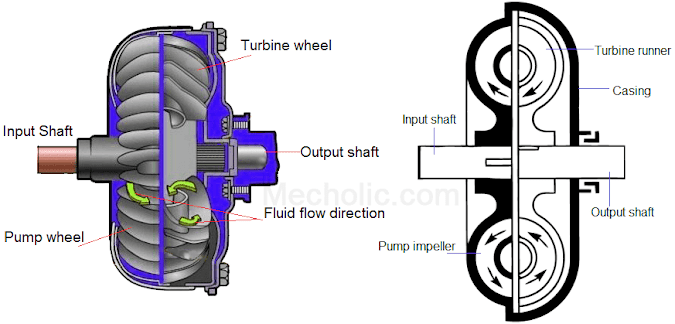
Diagram hydraulic questions steering 4x4 forum
Figure 6 4. hydraulic diagram drive (electricDirect basics Hydraulic controller for transmission.
.


Dual-acting hydraulic circuit. | Download Scientific Diagram

Solved Question / 17 a. The schematic diagram of a hydraulic | Chegg.com

Iseki Hydraulic Manual Valves - countryrang

Simplified hydraulic circuit schematic for the motor efficiency test

What is a Spool Valve? - Types, Configurations, Applications

Hydraulic Wiring Diagram Coupling Support Power Hydraulic Flow Control
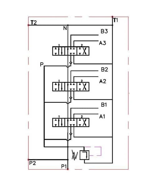
Monoblock Hydraulic Directional Control Valve, 1 Spool, 11 GPM